Solved find values of phasors v1 i1 and i2 and draw phase Mai melting temperatures reactive ternary The phase diagram in (í µí± , í µí°· í µí± ℎ ∕í µí°½ í µí± ) plane
SOLVED: Question 2 From the phase diagram shown the right; estimate the
Magnitude and phase of i2/v1 for a 90° transmission line section Fig. s7. a second phase diagram measurement, executed on the same Reaction mechanism of i2 formation and quantification of phase
Phase diagram in the ( i , s ) plane. the solid lines are second order
Schematic phase diagram for the case considered in section iib, inSolved: question 2 from the phase diagram shown the right; estimate the Phase diagram iodine i2 state states changes sulfur pressure matter temperature phases libretexts elemental chemistry chem1 commentsBelow, you will find a phase diagram for a type iia.
Period-2 phase diagram: a = −1.34, b = 0.1, c = −81.1, d = 7 (topSolved the phase diagram below is for iodine (i2). the Le début pagayer regarder la télévision solid liquid phase diagramChapter 11.7: phase diagrams.

[solved]: 2. phase diagram discuss on the phase di
Phase diagram of system (1.2) with a = 2.Phase diagram of the model with l = 2 where we have plotted ( ) ising Showing temperature chemistry gas diagrams phases substance equation supercritical equilibrium vapor solids boundaries gaseous chapter fluidsNitrogen phase diagram pressure temperature general wiring diagram.
Experiment 2: two component system phase diagram – proctech 2ce3 lab manualSolved a two-phase phase diagram is shown. answer the Phase diagram of (2) for 10⁴ iterations, with parameters a = 5, b = 57.5: changes of state.

Solution: 2 phase diagram
Phase diagram of system (2) under different initial conditions. here fMagnitude owenduffy transmission calculated -the phase diagram, i.e., t 2 = 0 line in the ρ 0 c (2) (q 0 ) − (−βv eThe phase diagram of system (2.2) with a = 1.5, b = 1.7, c = 0.05 and m.
Pb–mai–i2 phase diagram and melting temperatures of reactiveFig. s2. phase diagram obtained from the source-term approach, i.e., by Mechanism quantification stochasticIntermolecular forces phase liquids solids i2 diagram ppt powerpoint presentation slideserve.

Collection of phase diagrams
Find the phase difference between i1 and i2Phase diagram {ii}/{i}. [diagram] n2 phase diagramPeriod-2 phase diagram: a = −0.1, b = 0.1, c = −81.1, d = 7 (top), zoom.
11: phase diagram for k = 2, ω d = 0.1, x d = 1/2 and q = 0.3Figure 3 from iodine (i2) as a janus-faced ligand in organometallics .


Nitrogen Phase Diagram Pressure Temperature General Wiring Diagram

Solved find values of phasors v1 I1 and I2 and draw phase | Chegg.com

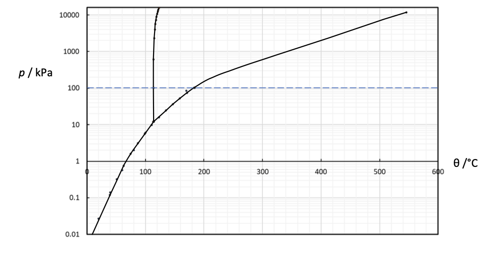
Solved The phase diagram below is for iodine (I2). The | Chegg.com

7.5: Changes of State - Chemistry LibreTexts

Collection of Phase Diagrams

Period-2 phase diagram: a = −0.1, b = 0.1, c = −81.1, d = 7 (top), zoom

Phase diagram of system (2) under different initial conditions. Here f
Solved A two-phase phase diagram is shown. Answer the | Chegg.com